


Product Summary:
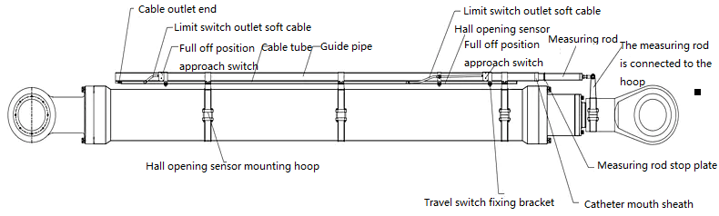
Gate opening (Hall magnetic gate) displacement sensor is one of the products of Hubei Miran Technology Co., LTD. Gate opening (Hall magnetic gate) displacement sensor is an external installation, the sensor is mainly composed of Hall sensor and measuring rod. The Hall sensor is 1300mm long, equipped with a guide sleeve, the cable is led out from the rear, and the guide sleeve is fixed on the oil cylinder using a hoop mounting base; The measuring rod is installed in the guide tube, the length of which is slightly larger than the measuring stroke. The measuring rod is connected with the measuring rod connected with the hoop installed on the lifting lug at the front of the cylinder. With the telescopic movement of the cylinder, the measuring rod also expands and moves in the guide tube, and the Hall sensor senses the gate opening signal. According to the practice of hydraulic engineering, when the piston rod is fully extended, the opening is "0" mm, and when the piston rod is fully indent, the opening is the largest.
- Product Overview
- Technical Parameters
- Size selection
Gate opening (Hall gate) Displacement sensor Overview:
Gate opening (Hall magnetic gate) displacement sensor is one of the products of Hubei Milang Technology Co., LTD. Gate opening (Hall magnetic gate) displacement sensor is an external installation, the sensor is mainly composed of Hall sensor and measuring rod. The Hall sensor is 1300mm long, equipped with a guide sleeve, the cable is led out from the rear, and the guide sleeve is fixed on the oil cylinder using a hoop mounting base; The measuring rod is installed in the guide tube, the length of which is slightly larger than the measuring stroke. The measuring rod is connected with the measuring rod connected with the hoop installed on the lifting lug at the front of the cylinder. With the telescopic movement of the cylinder, the measuring rod also expands and moves in the guide tube, and the Hall sensor senses the gate opening signal. According to the practice of hydraulic engineering, when the piston rod is fully extended, the opening is "0" mm, and when the piston rod is fully indent, the opening is the maximum.
Gate opening (Hall magnetic gate) displacement sensor application fields and characteristics:
● Suitable for water conservancy industry all kinds of gate opening, cylinder displacement measurement
● Suitable for vibration, motion working environment
● Highly waterproof seal, protection class IP68 ● Resistant to harsh environment, strong corrosion resistance
● Absolute value output ● A variety of signal output to choose from
● Anti-polarity selection, anti-static, anti-lightning, anti-surge, anti-corrosion, anti-vibration, anti-interference ability
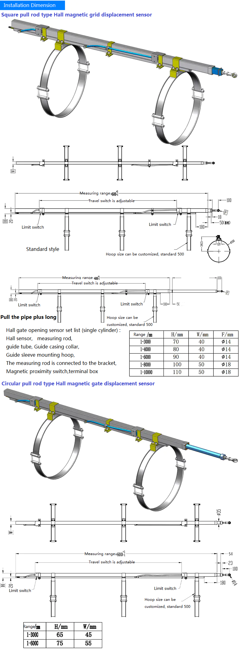
Gate opening (Hall magnetic gate) displacement sensor technical parameters and installation size:
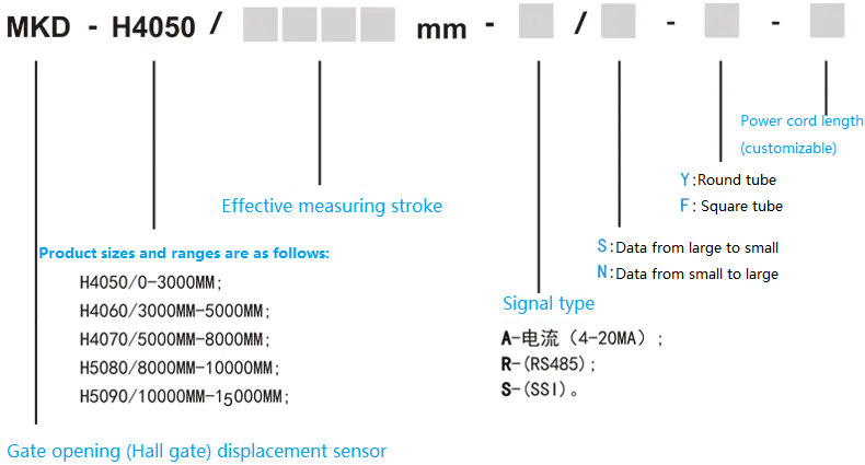
Model | MKD gate opening external tie rod type (hall magnetic grid ) displacement sensor | Effective travel | 0mm-15000mm |
Resolution | 1mm | Full Linearity | ≤±0.01%FS |
Repeatability | ≤±0.01%FS | Power supply | DC24V switching power supply, ≤100mA |
Output signal | 4-20mA,RS485,SSI, Serial synchronous digital signal | Lightning protection | Yes |
Working current | ≤50mA | Polarity protection | ≤-30Vdc |
Over voltage protection | ≤36Vdc | Insulation protection | DC500V( earthing of casing) |
Working environment temperature | -30℃~85℃ | Storage temperature | -45℃~90℃ |
Protection grade | IP68 | Anti-vibration | Omnidirectional amplitude ±5mm,5-250HZ,50G |
Installation direction | Vertical, tilt, horizontal | Way to install | Hoop (size can be customized) |
Material | SUS304 stainless steel(fresh water); SUS316 Stainless steel (sea water) | ||
Electrical connector | Waterproof cable connector outlet, line length standard 10 meters (line length can also be customized) | ||
Gate opening (Hall gate) displacement sensor selection:
Gate opening (Hall magnetic gate) displacement sensor installation diagram:
Gate opening (Hall magnetic gate) displacement sensor installation precautions:
1, before installation, check the assembly drawing, familiar with the name, installation position and installation points of each installation, and then refer to the drawings and installation instructions for installation. The following installation steps are general steps. Due to different site environments, the installation steps and methods can be flexibly adjusted according to the actual situation.
2, if the conditions are available, the gate can be opened and closed to the appropriate position for installation, generally the gate is fully open for the best installation position. According to the position marked on the installation drawing, weld the measuring rod connecting bracket to the piston rod lifting lug, and install the guide sleeve mounting collar on the cylinder. According to the actual situation, the installation position of the guide sleeve may not be strictly installed according to the position indicated on the drawing, and the distribution, force distribution and installation convenience shall prevail. However, the position relative to the guide sleeve and the cylinder shall not be changed. Otherwise, the sensor will be in the reading blind area when the gate is completely closed, or the sensor reading stroke is too much, and the designed measuring stroke cannot be reached after zero clearing.
3. Select the installation procedure according to the actual situation. During installation, you can assemble the guide sleeve and the hoop (assemble the guide sleeve and the hoop with the guide sleeve hoop) first, and then lift the two together to the oil cylinder, or install the hoop on the oil cylinder first, lift the sleeve to the oil cylinder, and then assemble the hoop. Generally, you can assemble the guide sleeve first, and then lift the hoop. When installing and hoisting the hoop, the opening should be oriented towards the side that is easy to install and fix. Do not tighten the screws before determining the position of the hoop. Adjust the guide sleeve to be directly above the cylinder and in a straight line, and then fix the screws.
4, installation precautions: (1), the measuring rod is printed with the "working face" logo, and the side with multiple sections of magnetic is the working face (metal can be adsorbed), such as the measuring rod is drawn out, the induction surface must be oriented towards the Hall sensor when reducing; (2), because the stainless steel pipe is smooth, the rope must be fixed firmly when hoisting and prevent falling;
5. After fixing the guide sleeve, move the measuring rod to the lifting lug of the gate, and connect the joint bearing on the measuring rod with the hoop support on the lifting lug. Note that the connecting hoop of the measuring rod must be in line with the guide sleeve;
6, if the gate is fully open or fully closed during installation, when connecting the measuring rod, you can check whether the "full scale marking line" on the measuring rod (view when fully open installation) or "zero mark line" (view when fully closed installation) is at the pipe mouth, and the marking line can be slightly entered into the tube (generally within 20mm into the tube, not too much, in case of insufficient travel), but it can not be exposed. If the marking line is exposed to the tube mouth, the measuring rod or guide sleeve should be adjusted so that it is not outside the tube mouth (on the premise of ample space, the adjustment of the measuring rod connection hoop is the simplest), this operation is to prevent the measuring rod from being in the Hall sensor detection blind area when it is fully closed; If the gate is not fully open or fully closed during installation, please install it according to the position marked on the drawing, align the guide sleeve with the cylinder mounting seat, see the installation drawing, and the position of the collar can be adjusted according to the situation;
7, install the junction box in the appropriate position, based on the installation, wiring convenience, effective protection prevail. Hall sensor, proximity switch cable through the pipe, connect to the junction box (the terminal in the junction box is defined by itself), and then connect to the electric control cabinet;
8. Connect the cable to the corresponding terminal in the electric control cabinet according to the installation instructions.
Gate opening (Hall gate) displacement sensor PLC debugging:
1, after the PLC is set, the sensor can be put into use, when the gate is fully closed, the sensor will generally have an initial value display, at this time through the PLC zero can be cleared, the sensor design measurement stroke will leave a margin, but if the initial value is too much, the value of the zero may be greater than the margin, the sensor will not be able to measure to the design stroke, such as after the gate is fully opened, If it is found that the full stroke cannot be measured, it is necessary to adjust the measuring rod or sleeve to reduce the invalid measuring stroke so that the sensor can reach the designed stroke; If there is no initial value when the gate is fully closed, and the data can be read only after the gate has been opened for a period of time, it indicates that the Hall sensor is in the blind area when the gate is fully closed. At this time, the gate should be fully closed, and the position of the measuring rod or guide sleeve should be adjusted according to the method of item 6 of "Product Installation" above, using the zero mark line as a reference, so that the mark line is slightly inserted into the pipe port, or according to the actual opening display on the PLC. Adjust the opening data to within 100mm, and then clear it on the PLC. Note that when opening the door for the first time, it is necessary to observe the operation status of the measuring rod throughout the whole process. If it is not in a straight line with the guide sleeve, or other anomalies occur, it should be stopped immediately for inspection and adjustment;
2. If the Hall sensor is loose during installation and debugging or replaced, the induction surface of the Hall sensor (marked by the tube body) must be oriented towards the guide sleeve when restoring; If the measuring rod is extracted, the induction surface (the side with multiple magnetic segments) should be oriented towards the Hall sensor during reduction.