


Product Summary:
LVDTC36 valve core displacement sensor using differential transformer LVDT principle for measurement, DC LVDT has excellent performance, the use of convenient single power supply +12 ~ 28V DC power supply, Electronic circuit sealed in 304 stainless steel metal tube, can work in the humidity and dust and other harsh environment, the output signal for the standard can be used by the computer or PLC voltage 0-5V, 0-10V, current 4-20mA and RS485 digital signal, can withstand 35Mpa high voltage. Widely used in hydraulic control field, proportional valve, servo valve, reversing valve, macro servo cylinder, etc.
- Product Overview
- Technical Parameters
- Size selection
I. Overview:
LVDTC36 spool displacement sensor adopts differential transformer principle to measure, DC LVDT has excellent performance, the use of convenient single power supply +12 ~ 28V DC power supply, Electronic circuit sealed in 304 stainless steel metal tube, can work in the humidity and dust and other harsh environment, the output signal for the standard can be used by the computer or PLC voltage 0-5V, 0-10V, current 4-20mA and RS485 digital signal, can withstand 35Mpa high voltage. Widely used in hydraulic control field, proportional valve, servo valve, reversing valve, macro servo cylinder, etc.
II. Characteristics:
● Adopt mechanical zeroing, zeroing range 2mm, abandon the traditional potential zeroing method
Technical parameter
| LVDTC36-40mm |
Measuring range | 0-40mm |
Output signal | 0~5V,0~10V,4~20mA,RS485 |
Resolution | 0~10V,4~20mA is 1um ; 0~5V is 2um;RS485 is 16bit |
Linear error | ≤1% |
Repeat error | Up to 1um |
Power supply | 12~28V DC |
Working current | 3.9~22mA |
Dynamic performance | 50Hz |
Excitation voltage | 3Vrms |
Excitation frequency | 5KHZ |
Temperature coefficient | Zero≤0.01%/℃ |
· Resistance to pressure | 35Mpa |
Zero calibration | Zero range mechanically 2mm |
Operating temperature | -25℃~+85℃ |
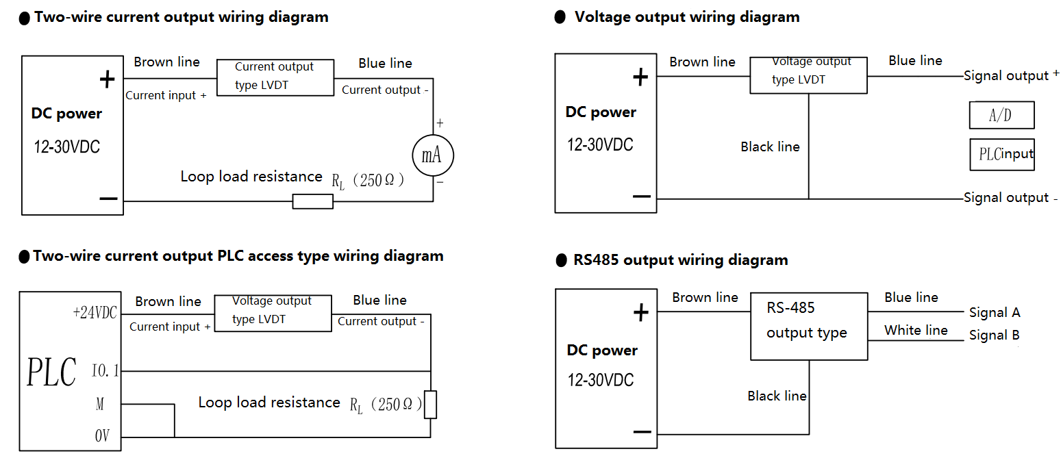
IV.Mode of connection:
| Brown | Black | Blue | White | Shielded wire |
3 wires voltage | 12~28V DC | 0V or signal negative | 0~5V, 0~10V | 0V or signal negative | Connect the ground |
2 wires current | 12~28V DC | NC | 4~20mA | NC | GND |
4 wires RS485 | 12~28V DC | 0V | Signal A+ | Signal B- | GND |
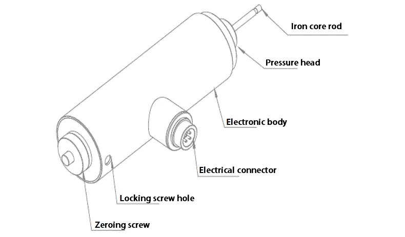
VI, Instructions:
1. Put the iron core connecting rod into the spool and lock the screw.
2. Cover the pressure tube with the iron core connecting rod and put the locking screw into the valve block.
3. The main part of the sensor is set on the pressure tube, and the zero screw is installed.
4, plug in the connection line and supply 24V to the sensor, make the sensor work normally, can be connected to the voltmeter or ammeter to monitor the output signal, turn zero screw, move the sensor internal coil on the position of the voltage tube, generally to half of the range as the starting point of the installation test, that is, the voltmeter, The ammeter output is 2.5V if it reads 0-5V, 5V if it reads 0-10V, and 12mA if it reads 4-20mA.